2nd Oct 2026
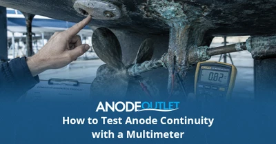
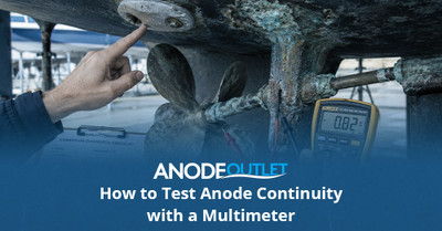
A continuity test checks whether a low-resistance electrical path exists between a sacrificial anode and the metal it is intended to protect. With the boat safely isolated and the meter set to its lowest resistance range, place one probe on a clean point connected to the anode and the other on clean bare metal of the protected component. A stable reading close to the resistance of the test leads indicates a conductive path; an open, unstable or much higher reading indicates poor contact or a break that needs investigation.
This test does not prove that the anode alloy is correct, that it produces enough protective current or that the boat is at the correct potential in the water. Those questions require model information and, when necessary, in-water testing with a reference electrode.
Use this method after fitting hull anodes, checking drive continuity straps, inspecting shaft bonding or diagnosing an anode that has not worn.
Electrical safety
Do not perform resistance or continuity tests on an energised circuit. Disconnect shore power through the proper procedure, isolate batteries and equipment as required, and never remove a protective-earth conductor. Complex vessels should be tested by a qualified marine electrician.
Contents
- What a continuity test can and cannot show
- What you need
- Prepare the boat and meter
- Test a directly mounted anode
- Test a remotely bonded hull anode
- Testing shaft and propeller continuity
- Testing saildrive, sterndrive and outboard straps
- How to interpret the reading
- Common causes of failed continuity
- Why continuity is not the same as an in-water anode test
- After the test
- Frequently asked questions
- Technical references
What a continuity test can and cannot show
| The test can help show… | The test cannot prove… |
|---|---|
| Whether two accessible points have an electrical connection | That the anode material is correct for the water |
| Whether paint, corrosion or a loose connection has created an open circuit | That anode area or mass is sufficient |
| Whether a bonding wire or drive strap is broken | That every protected component is connected exactly as intended |
| Whether a flexible coupling interrupts the shaft path | That the in-water cathodic-protection potential is correct |
| Whether an installation improved after cleaning contact faces | That no stray-current fault exists |
Continuity is therefore a screening test. It confirms one necessary condition for a sacrificial anode to protect a remotely connected component, but not the complete electrochemical performance.
What you need
- A digital multimeter with a low-ohms range and audible continuity function.
- Sharp, clean probes or suitable clips that can reach bare test points.
- A short known-good test lead or extension for distant hull components.
- Fine abrasive pad or approved cleaning tool for test points only.
- Equipment diagrams showing the intended bonding path.
- Labels or photographs so disconnected wires are restored correctly.
- Personal protective equipment suitable for the work area.
A basic meter is sufficient to find an open circuit, but readings at fractions of an ohm can be dominated by lead and probe contact resistance. Do not claim false precision from an inexpensive instrument.
Prepare the boat and meter
- Confirm the intended system. Identify which anode should protect which component. A nearby anode is not necessarily connected.
- Haul out or use safe accessible test points. Do not work in water near energised shore-power systems.
- Disconnect shore power correctly. Unplug and secure the lead according to marina procedure.
- Isolate battery and DC circuits as required. Follow equipment manuals; retain essential safety or memory supplies only where the test plan permits.
- Remove sensitive parallel paths if instructed. Active corrosion controllers and electronics can affect readings and may require model-specific isolation.
- Inspect physically first. Look for broken straps, loose bolts, paint, corrosion and damaged cables.
- Set the meter to resistance. Touch the probes together and record the lead/contact resistance before testing the boat.
Record lead resistance
If the shorted probes read 0.3 ohm, a boat reading of 0.3–0.4 ohm may represent very little additional resistance. Subtracting mentally is useful, but probe contact and meter accuracy still limit precision.
Test a directly mounted anode
A shaft collar, drive anode or bolt-on anode may make direct contact through its insert, bolts or mating face. The exact test points depend on the design.
- Choose a clean metallic point on the anode insert, fixing or designed contact—not a heavily oxidised sacrificial surface if a better point is available.
- Choose a clean bare point on the component immediately protected by the anode.
- Press the probes firmly and wait for a stable reading.
- Reverse the probes and repeat to expose poor contact or electrical effects from connected equipment.
- Move one probe to several points on the component to check that joints are conductive.
- Compare the result with the shorted-lead reading and a direct piece of known metal.
If the meter shows open circuit, remove the anode and inspect paint, sealant, oxide, distorted inserts and bolts that bottom before clamping. Clean only the intended contact area and refit with correct anode bolts and fittings.
Test a remotely bonded hull anode
On GRP or wooden boats, a hull anode may be bolted outside and connected internally by wires or studs to a shaft, rudder or other underwater system. Test the chain in sections rather than only from end to end.
| Test pair | What it checks |
|---|---|
| Anode stud to internal cable terminal | Stud, washer and cable-lug contact. |
| Cable terminal to next bonding junction | Cable continuity and intermediate connectors. |
| Across a flexible shaft coupling bridge | Whether the coupling bypass strap/brush is functioning. |
| Gearbox/shaft connection to propeller shaft | Shaft bonding or electro-eliminator path where designed. |
| Anode stud to rudder stock or protected fitting | Complete end-to-end path. |
A good end-to-end reading can hide two parallel paths, one of which is broken. Physical inspection and sectional tests remain important.
Testing shaft and propeller continuity
A direct-fit shaft anode should have close, clean contact with the shaft. Test between an appropriate point on the anode/insert and clean shaft metal. For a remotely bonded hull anode, the path may cross the gearbox coupling through a bonding strap or shaft brush.
- Rotate the shaft slowly while observing a brush or electro-eliminator reading; intermittent contact can appear at certain positions.
- Inspect carbon brushes, springs and slip surfaces for wear or contamination.
- Do not put probes where the shaft can move unexpectedly.
- Confirm that propeller hubs, rope cutters and flexible couplings are part of the intended circuit before assuming continuity.
- Use the existing shaft-anode fitting guide for direct mechanical fit and clearance.
Testing saildrive, sterndrive and outboard straps
Drives can contain several painted, moving or rubber-isolated housings. Manufacturer-fitted straps bridge those joints. Test each strap from clean terminal to clean terminal and then test the complete connected housing path.
| Finding | Interpretation |
|---|---|
| Low stable reading across strap | Conductive at the tested moment; still inspect strands and flexing. |
| Open circuit | Broken strap, loose terminal, paint or corrosion at contact. |
| Reading changes as drive steers or trims | Intermittent cable/strap fatigue or terminal movement. |
| Good strap but isolated housing | Another joint or paint layer interrupts the path. |
| Good continuity but housing corrodes | Investigate alloy, anode capacity, coating, active system and in-water potential. |
Active systems such as MerCathode require separate tests. Do not measure through a controller with an ohmmeter unless its procedure explicitly permits it.
How to interpret the reading
The desired result is generally a stable reading only slightly above the shorted-lead/contact resistance, consistent with a robust metallic path. There is no single universal resistance number that can be applied blindly to every boat, meter and circuit.
| Meter behaviour | Likely meaning | Next step |
|---|---|---|
| Stable, close to lead resistance | Good conductive path at the tested points | Inspect physically and proceed to other system checks. |
| Open / OL | No path or probes not contacting bare metal | Verify probe points, then trace the circuit section by section. |
| High but stable | Resistive joint, long/thin conductor or unintended path | Clean/repair connections and compare with design. |
| Fluctuating when probes are still | Poor probe contact, corrosion, loose connection or parallel electronics | Improve test points and isolate affected equipment correctly. |
| Reading changes with movement | Intermittent strap, brush, cable or connection | Repair the moving/flexing component. |
Audible continuity buzzers often sound at resistance values far higher than desirable for a bonding path. Read the numerical display rather than treating a beep as proof.
Common causes of failed continuity
- Paint, antifouling, sealant or grease under the anode or cable lug.
- White oxide or corrosion scale on aluminium or zinc contact surfaces.
- Loose, stretched or wrong-length anode bolts.
- Broken drive continuity straps.
- Corroded ring terminals or bonding cables.
- Flexible shaft coupling installed without the designed bridge.
- Worn shaft brush or electro-eliminator.
- Anode mounted close to a component but never electrically bonded to it.
- Threadlocker or tape covering a required conductive interface.
- A replacement anode with a different insert or mounting profile.
After repair, retest the individual joint and the complete path. Photograph clean contact surfaces before assembly and record the final reading and meter lead resistance.
Why continuity is not the same as an in-water anode test
Cathodic protection is assessed electrochemically by measuring the potential of the protected metal relative to a stable reference electrode in the surrounding water. The acceptable range depends on the metal, coating and system. This test reveals under- or overprotection that a resistance test cannot.
In-water testing should be performed at representative locations and operating states, such as shore power connected/disconnected and DC equipment on/off. Interpretation requires training because reference-electrode type, distance, water conditions and electrical configuration affect the result. See cathodic-protection voltages for background.
Two different questions
Continuity test: Is there an electrical path?
Reference-electrode test: Is the protected metal at an appropriate potential in the water?
After the test
- Reconnect every cable, strap and equipment connector exactly as documented.
- Restore battery and shore-power systems through the correct safe sequence.
- Check that seacocks, drive supports and other service isolations are returned to operating condition.
- Record readings, probe points, meter model and lead resistance.
- Inspect the boat after relaunch and arrange in-water testing when the original fault involved corrosion.
- Monitor anode wear earlier than usual to confirm the repair was effective.
Restore reliable mechanical contact
Replace damaged anodes and fitting hardware with application-correct parts after the cause has been identified.
Frequently asked questions
What resistance should there be between an anode and protected metal?
It should be a stable, very low resistance close to the meter lead/contact resistance for a direct conductive path. Use the equipment specification where provided rather than a universal internet number.
Can I test an anode while the boat is in the water?
Resistance tests are normally clearer with circuits isolated and accessible ashore. In-water performance is assessed with a reference electrode, not by putting an ohmmeter across seawater.
Why does my meter beep but show several ohms?
Continuity buzzers use a broad threshold. Several ohms may still trigger a beep but indicate a poor path compared with a clean metallic connection.
Can I test through antifouling paint?
No. Use legitimate clean metal test points. Do not damage coatings randomly; select intended studs, terminals or exposed component points.
Does a zero-ohm reading mean the boat is protected?
No. It confirms connection at the test points. The anode may still be wrong, depleted, undersized, out of the water or unable to achieve correct in-water potential.
Should I disconnect electronics before testing resistance?
Follow the system and equipment procedures. Parallel circuits and active-corrosion controllers can affect readings or be damaged by inappropriate testing.